555 Timer Schematic Diagram / Schematic Circuit Diagram Astable Multivibrator Using 555 Timer Proteus Simulation - The 4rth circuit diagram shows the standard ic 555 adjustable timer circuit having two sets of timing ranges and an output relay for toggling the desired load.
555 Timer Schematic Diagram / Schematic Circuit Diagram Astable Multivibrator Using 555 Timer Proteus Simulation - The 4rth circuit diagram shows the standard ic 555 adjustable timer circuit having two sets of timing ranges and an output relay for toggling the desired load.. This circuit uses very basic components like 555 timer and 4017 counter. An external triggering is required for transition from stable to unstable state. The second 555 timer helper will extend the timers output duration without having to use large values of r1 and/or c1. The breadboard schematic of the above circuit is shown below. There are simple circuits for beginners and advanced engineers.
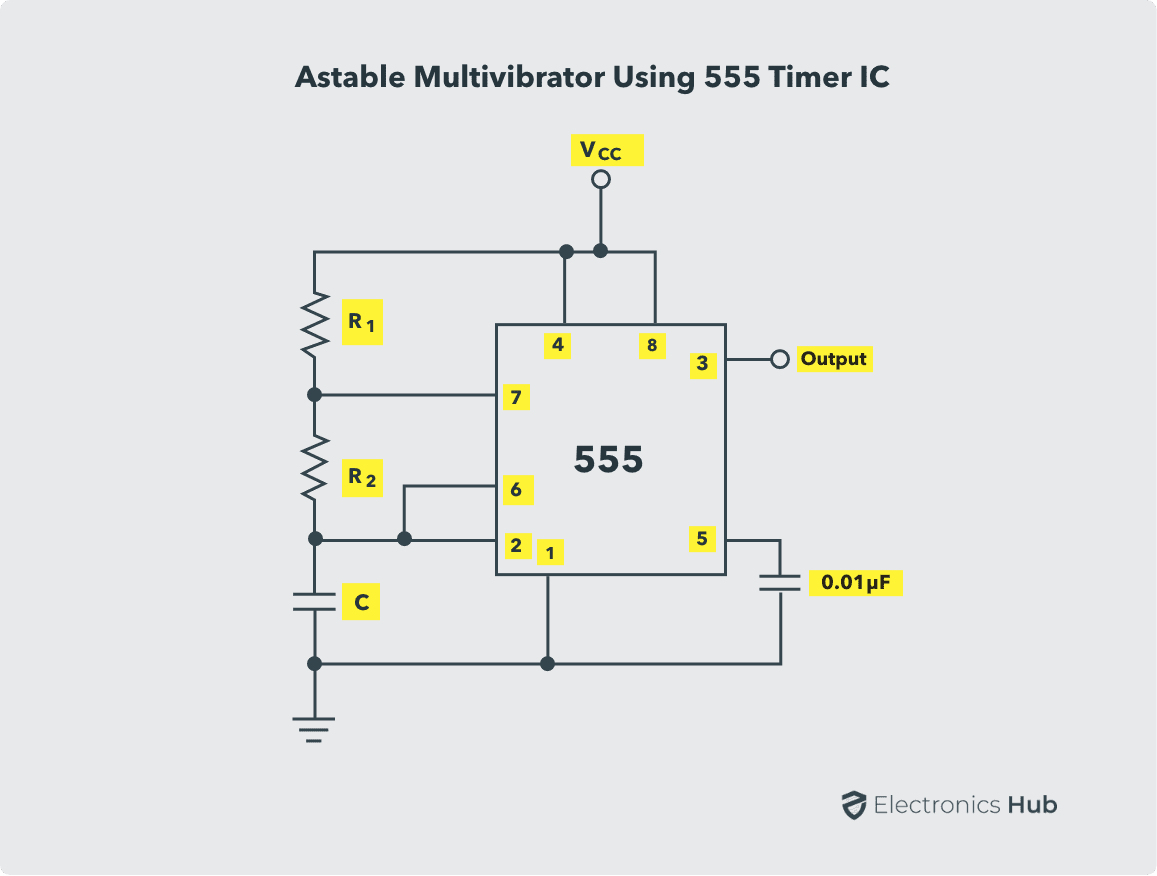
This controlling can be done by selecting the appropriate values for the resistor r1,r2 and capacitor c1. Blinking led using 555 timer. The values of r1 and c1 determine how long the output will remain high. You can use it for the snooze alarm with a buzzer. Adjustable on off timer(using 555 astable mode) in this circuit a timer with cyclic on off operations is designed.
12v To 230v Inverter Circuit Diagram Using 555 Timer Ic Inverters from i1.wp.com Let us discuss in detail about this circuit. 555 timer was first introduced by signetics corporation in 1971 as se555/ne555. These on off intervals can be adjusted by varying the 555 timer output and number of counter outputs. It monitors the charging of the timing capacitor in astable and monostable circuits. A collection of 555 circuits using the 555 timer as an astable oscillator with different duty cycles. The next diagram shows the basic current consumption of 555 timer chips from different manufacturers. You can use it for the snooze alarm with a buzzer. The 555 timer starts timing when switched on.
The 555 timer delay before turn on circuit we will build is shown below.
Although the schematic looks correct, this basic circuit may actually have a few negative aspects. Its name is derived from three 5k ohm resistors ,connected in series used in it.the timer ic can produce required waveform accurately. The longer lead of a polarized capacitor is the positive and the shorter lead is negative. In 2017, it was said over a billion 555 timers are produced. 555 timer circuits (133) browse through a total of 133 555 timer circuits and projects including the timer's datasheet. Also… if you want to control other loads. 555 timer ic remains in stable state until the external triggering is applied. Some devices will not function properly if the current to the threshold input is not restricted. Figure 2 shows the basic 555 timer monostable circuit. An external triggering is required for transition from stable to unstable state. 555 timer is an industrial standard ic existing from early days of ic. The breadboard schematic of the above circuit is shown below. Working modes of 555 timer ic.
With this information you will learn how how the 555 works and will have the experience to build some of the circuits below. 500ms is the same as saying 0.5s so by rearranging the formula above, we get the calculated value for the resistor, r as: In this circuit, after you press the button once, the led will light up then turn off. This integrated circuit can be used in a variety of ways from which the basic one is to produce accurate and stable delays in electronic circuits.additionally, it is available in 8 pin dip and 14 pin dip. This circuit uses very basic components like 555 timer and 4017 counter.
How 555 Timers Work The Learning Circuit Youtube from i.ytimg.com This circuit uses very basic components like 555 timer and 4017 counter. This integrated circuit can be used in a variety of ways from which the basic one is to produce accurate and stable delays in electronic circuits.additionally, it is available in 8 pin dip and 14 pin dip. The 555 timer ic is an integral part of electronics projects. With this information you will learn how how the 555 works and will have the experience to build some of the circuits below. The values of r1 and c1 determine how long the output will remain high. It monitors the charging of the timing capacitor in astable and monostable circuits. As the name indicates, only one state is stable and the other one is called unstable or quasi stable state. Because of their availability and ease of use, the 555 astable circuit is the common source of clock signal in many synchronous circuits.
Blinking led using 555 timer.
It monitors the charging of the timing capacitor in astable and monostable circuits. A collection of 555 circuits using the 555 timer as an astable oscillator with different duty cycles. 555 timer is an industrial standard ic existing from early days of ic. In the place of the push switch s1 / trigger switch you can also connect the output of any project to trigger the timer. In this mode, the circuit of the ic 555 timer produces the continuous pulses with exact frequency primarily based on the value of the two resistors and. It is easy to make and portable with small pcbs. The breadboard schematic of the above circuit is shown below. A monostable 555 timer is required to produce a time delay within a circuit. In 2017, it was said over a billion 555 timers are produced. This circuit uses very basic components like 555 timer and 4017 counter. The circuit symbol for a 555 (and 556) is a box with the pins arranged to suit the circuit diagram: The longer lead of a polarized capacitor is the positive and the shorter lead is negative. 555 timer ic remains in stable state until the external triggering is applied.
An external triggering is required for transition from stable to unstable state. 555 one shot timer | circuit diagram. This pin is either grounded or connected to the negative rail. 555 ic timer block diagram 555 ic timer block diagram. The second 555 timer helper will extend the timers output duration without having to use large values of r1 and/or c1.
Astable Multivibrator Using 555 Timer Circuit Duty Cycle Applications from www.electronicshub.org This integrated circuit can be used in a variety of ways from which the basic one is to produce accurate and stable delays in electronic circuits.additionally, it is available in 8 pin dip and 14 pin dip. Basic 555 monostable multivibrator circuit. The 555 timer ic is an integral part of electronics projects. Because the output of 555 has a maximum current to 200ma. Connect pin 1 of a 555 timer ic to the ground. Simple 555 timer circuits & projects. 555 or 1/2 556 discharge control voltage threshold trigger reset r r r vcc output output sl00954 figure 1. In this video we look at a simple 555 astable circuit.
A collection of 555 circuits using the 555 timer as an astable oscillator with different duty cycles.
Basic 555 monostable multivibrator circuit. Collect all the required components and place the 555 timer ic on the breadboard. It monitors the charging of the timing capacitor in astable and monostable circuits. A collection of 555 circuits using the 555 timer as an astable oscillator with different duty cycles. The 555 ic timer circuit above shows a very straightforward design where the ic 555 forms the central controlling part of the circuit. 555 ic timer block diagram 555 ic timer block diagram. It is easy to make and portable with small pcbs. In this video we look at a simple 555 astable circuit. 555 datasheet 555 duty cycle 555 metronome 555 reset function 555 time delay relay inverted 555 timer pulse generator. Because of their availability and ease of use, the 555 astable circuit is the common source of clock signal in many synchronous circuits. We connect a 100μf capacitor to the positive voltage supply and then to pin 2. 555 timer helpers schematic the addition of a capacitor to the trigger will not work for short output pulses as there is also a short delay in the recovery of the trigger terminal voltage. 555 timer circuits (133) browse through a total of 133 555 timer circuits and projects including the timer's datasheet.


0 Komentar